Gears Drive the World!
- Wolfgang A. Haggenmüller

- Jan 29, 2025
- 21 min read
Updated: Jan 30, 2025

The topic of gearing covers several central aspects, including the classification of gears, manufacturing techniques, design criteria, quality requirements, material and current trends in technology development. Gears are critical for power transmission and motion control in a wide range of machines and systems, from automotive to precision engineering. Gears are essential mechanical elements for power transmission and motion control. They can be found in a wide range of machines and systems, where they meet different requirements. This scientific paper examines in detail the different types of gearing, their classification and applications, as well as manufacturing techniques and design criteria.
1. Basics of Gearing: Classification and Types
Gears are used to transmit torques and rotary movements between shafts. Their geometry is crucial for the efficiency, precision and service life of the gearbox.
1.1 Classification and classification of gears
Gears are essentially divided into the following types:
Cylindrical gears: These include spur gears and helical gears.
Bevel gears: Include bevel gears, especially straight and helical bevel gears.
Worm and screw gears: Typical for worm gear gears, in which a screw acts on a gear.
Hypoid gears: A special type of bevel gear in which the axes are offset.
Planetary gearboxes: Often used for applications where high torque transmissions and compact designs are required.
The types of gears are also classified according to profile shape, e.g. involute gears and cycloidal gears. Involute profiles are the most common due to their manufacturing capabilities and load-bearing capacity.
Main types of gears

Cylindrical gears
Cylindrical gears: Cylindrical gears consist of teeth parallel to the axis and are often used in mechanical engineering applications. They are easy to manufacture and efficient at medium to high speeds. Features: Straight toothed, axes are parallel to each other. Advantages: Easy to manufacture, quiet in operation at low speeds. Application: Often used in mechanical engineering and automotive industry.
Helical gears: Here, the teeth are arranged at an angle to the axis, which enables more uniform power transmission and smoother running. Helical gears are used in gearboxes where high speeds and low noise are required. Characteristics: Teeth are inclined at an angle to the axis. Benefits: Ensures smoother load transfer and smoother running. Application: Often used in transmissions of vehicles and machinery.
Bevel gears
Features: Conical shape, axes are generally at a 90° angle to each other. Advantages: Allows torque to change direction. Application: Often used in differential transmissions and other applications where axle displacement is required.
Straight bevel gears: These have straight teeth and are suitable for applications where the shafts form a fixed angle, usually 90°. They offer precise and easy power transmission.
Spiral bevel gears: These provide a larger contact area between the teeth and are well suited for applications that require higher speeds and torques.
Hypoid gears are a special form of tapered gears in which the axes do not intersect at the same point. The staggered arrangement creates a larger overlap, which allows for higher torque transmission. Hypoid gears are often used in differential gears of vehicle axles.
Worm gears
Worm gears consist of a helical worm and a worm gear, which are suitable for applications with high gear ratios. They can be found in lifting devices, conveyor systems and, in some cases, in gearboxes for robotics and precision mechanics, as they can also offer self-locking. Features: A worm gear consists of a worm wheel and a worm that are perpendicular to each other. Advantages: High gear ratios and self-locking possible. Application: In hoists, conveyors and lathes.
Planetary gearboxes (epicycloidal gearboxes)
Planetary gearboxes consist of a central gear, planetary gears and a ring gear. These gears enable high gear ratios in a compact design and are often used in automotive transmissions, machine tools and wind turbines. Features: A central sun gear around which several planetary gears revolve. Advantages: High gear ratios, compact design and even force distribution. Application: Often used in automatic transmissions, drills and robotics applications.
Crown wheel
In the crown gear (also called crown wheel), the teeth are perpendicular to the wheel axis and protrude upwards or outwards like a crown. In contrast to conventional cylindrical gears, which have a straight or oblique toothing, the gearing of crown gears is particularly designed for right-angled axis arrangements (90°). Crown gears allow power to be transmitted between two axes, which are normally perpendicular to each other. They offer less slip and can transmit torques efficiently. Crown gears are easy to manufacture and allow for a compact design. They are especially useful in applications where a change in the direction of movement is required. Applications: Crown gears are often found in old movements, certain types of differential gears, and small mechanical devices. Today, however, they are rarely used, as they have been replaced by bevel gears and other more precise gear shapes. Features: Has gear teeth that are perpendicular to the wheel axis. Advantages: Allows for a compact design and is efficient for 90° angular transfers. Application: Less common, but sometimes used in special mechanisms.
Internal teeth
Internal gears (also called internal gears) are gears in which the gears are attached to the inside of the wheel. They often engage an external cylindrical gear or planetary gear, with the teeth of the internal gearing pointing inwards. Internal gears allow multiple gears to work together in a confined space. This results in a more compact design and reduces the dimensions of the gearbox without reducing the gear ratio or load capacity. Due to the arrangement of the gears inside, the gear pair is very compact and stable, and the load transfer is evenly distributed. Internal gears also reduce axial backlash and noise. They are often used in planetary gearboxes, where they work together with sun and planetary gears to make the gearbox efficient and space-saving. Internal gears are also found in various machine transmissions, vehicle drives, and industrial applications. Features: Gears with the teeth on the inside. Advantages: Compact design, especially in combination with planetary gearboxes. Application: In planetary gearboxes and compact transmission systems.
1.2 Gear profiles
Gears can also be differentiated according to the profile of the teeth:
Involute gears: Involute profiles have the advantage that when the center distance changes, the contact line and thus the engagement situation of the teeth does not change significantly. This makes them particularly suitable for industrial applications.
Cycloidal gears: Cycloidal profiles offer higher strength compared to involute gearing and are often used in heavy-duty applications, such as precision planetary gears or precision mechanics.
2. Gear Classes: Definition and Application
The quality of gears is divided into quality classes according to the DIN 3960/61 standards . This classification is crucial for the selection and application of the gear, as it has an influence on the accuracy, smoothness and performance of the gearbox.
High-Precision Gears (Grades 3-5)
Used in applications that require high accuracy and smoothness, e.g. in aviation and precision machinery. The tooth flank tolerances are 0.001 to 0.005 mm.
Standard Gears (Grades 6-8)
Commonly used in the automotive industry, e.g. for vehicle transmissions. Tolerances of 0.01 to 0.05 mm are achieved here, which is sufficient for applications that require good efficiency but not extremely high precision.
Simple Gears (Grades 9-12)
These are often used in agricultural machinery or conveyor applications. They have tolerances of 0.05 to 0.1 mm and offer a robust and cost-effective solution suitable for low to medium speeds.
Typical features of high-precision gears are minimal tolerances and a high level of smoothness. These are achieved by grinding and fine grinding. Simpler gears, on the other hand, are often milled or produced by casting.
3. Manufacturing Methods for Gears: Detailed Description of the Processes
The choice of manufacturing technology is based on the desired precision, costs and mechanical requirements. Each type of gear requires special manufacturing techniques.
Mill
Push
Grind
Axialfomen
Rolling
The production of gears involves various processes that differ in precision, cost, production speed and suitability for specific applications. In addition to axial forming, which offers a cost-effective and efficient alternative for series production, there are other established manufacturing processes. These include hobbing, gear shaping, gear grinding, broaching, and forging. Each of these procedures is described in detail below.
3.1 Hobbing
Gear hobbing is the most commonly used method for the production of gears. It is based on the relative motion of a rotating cutter and the workpiece, which continuously feed each other to create the desired tooth profile. Suitable for simple cylindrical spur gears, helical gears and bevel gears. Milling is cost-effective and allows sufficient accuracy for standard applications.
Process flow:
Tool selection: A special hob is selected whose tooth shape corresponds to the later profile of the gears.
Positioning and rotation: The workpiece and the milling cutter are clamped in a defined position in relation to each other. The cutter and workpiece rotate synchronously to create a continuous cutting motion.
Rolling movement: During the milling process, the workpiece moves axially along the milling cutter, cutting the tooth profile piece by piece.
Finishing: For precise requirements, grinding or surface treatment can follow.
Pros:
Flexibility: Can be used for different gear types and profiles.
Precision: Enables high dimensional accuracy and surface qualities.
Cost: Cheap in series production.
Typical applications: Hobbing is ideal for gears in transmissions and drive shafts of automobiles, machine components, and large-scale equipment.
Challenges:
Tool wear: Hobs wear out quickly on harder materials.
Risk of warping: For workpieces with low thickness, the milling process can lead to deformations that must be taken into account.
3.2 Gear shaping
Gear shaping is a process in which the tooth flank incision is made vertically, i.e. from top to bottom (or vice versa). It is particularly suitable for internal gears and hard-to-reach tooth profiles, as it works through an oscillating tool movement.
Process flow:
Tool selection: A slotting tool is used that is matched to the desired tooth profile.
Oscillating Motion: The tool moves axially up and down as the workpiece is rotated to carve out the tooth profile piece by piece.
Rolling movement: The workpiece rotates synchronously with the slotting tool to maintain contact continuously.
Finishing: Additional grinding may be necessary for precision requirements.
Pros:
Suitability for internal gearing: Can produce complex internal gears and profiles that are difficult to achieve with other methods.
High degree of precision: Particularly suitable for tightly tolerated profiles.
Typical applications: Gear shaping is often used for planetary gears and internal gears of transmissions in the automotive industry.
Challenges:
Limited speed: Due to the oscillating motion, the process is slower than hobbing.
High tooling: Requires special slotting tools that need regular maintenance and sharpening.
3.3 Generating grinding
Generating grinding is a high-precision manufacturing process used for the finishing of gears. The grinding process can achieve extremely fine surface qualities and low tolerances, making the process attractive for demanding applications such as high-performance gearboxes. Grinding is used for high-precision gears with low roughness values and low tolerances. It is typically used in bevel gears and hypoid gears that require high load capacity.
Process flow:
Grinding wheel selection: A precise grinding wheel, often made of carbide or with diamond grit, is selected.
Synchronization: The workpiece and grinding wheel rotate synchronously to ensure continuous rolling motion.
Material removal: The grinding wheel removes small layers of material and smoothes the tooth flanks, achieving high surface qualities.
Cooling: Due to the high frictional heat, continuous cooling is required.
Pros:
Excellent surface quality: Generating grinding allows for a very smooth tooth flank, which reduces friction and wear.
High dimensional accuracy: The process is ideal for precise applications and tight tolerances.
Typical applications: High-precision transmissions, such as those used in the automotive industry, aircraft technology and precision mechanical engineering, benefit from this process.
Challenges:
Costs: High costs due to abrasive tools and coolant.
Slow machining: The grinding process is time-consuming and is mostly only used for finishing.
3.4 Rooms
Broaching is a process that is especially suitable for series production and for large workpieces. A so-called broaching tool is used, which consists of several teeth arranged one behind the other to form the tooth profile in one pass.
Process flow:
Tool selection: The broaching tool is adapted to the desired tooth profile.
Introduction of tool: The workpiece is clamped into a holder, and the broaching tool is pulled or pushed through the workpiece.
Profiling: The successive cutting edges of the broaching tool gradually remove material and create the final tooth profile in one pass.
Finishing: After broaching, polishing or sanding may be necessary.
Pros:
High production speed: The tooth profile is formed in a single operation.
Low post-processing: No additional machining is required for less precise applications.
Typical applications: Broaching is often used for axles and drive shafts in vehicles as well as for large gearboxes.
Challenges:
Tool costs: Broaching tools are expensive and must be adapted exactly to the workpiece.
Limited flexibility: Since broaching tools can only cut a specific profile, the process is less suitable for small batches.
3.5 Forging
Forging is a shaping process in which a workpiece is shaped into the desired shape under heat and pressure. This method is particularly suitable for the production of raw parts that are later processed.
Process flow:
Heating of the workpiece: The workpiece is heated to a temperature at which it becomes deformable.
Forming: The workpiece is pressed into a shape that specifies the tooth profile. A die is often used to depict the desired tooth structure.
Cooling and Hardening: The forged workpiece is cooled and can be hardened if needed to increase strength.
Post-processing: The gears are milled, ground or scraped to achieve the desired final geometry and surface quality.
Pros:
High strength: Forging leads to solidification of the material, which makes the components extremely resistant.
Low material loss: As the material is pressed into the desired shape, the loss remains minimal.
Typical applications: Large and highly loaded gears, such as in agriculture, mechanical engineering and heavy industry.
Challenges:
Energy-intensive: Forging requires high temperatures and is therefore energy-intensive.
Risk of warping: The high heat and pressure can lead to material warping, which is why finishing is often necessary.
3.6 Axial Forming – A Special Manufacturing Technology for Gears
Axial forming is an innovative process for the production of gears and is particularly well suited for series production. It combines high accuracy with an efficient production speed and is particularly suitable for small and medium-sized gears, such as those often used in the automotive industry or in power tool manufacturing. In this process, the teeth are stamped or shaped into the workpiece by an axial movement without removing any material.
Axial Forming Properties
Axial forming makes it possible to produce complex tooth profiles with minimal material loss and in relatively short cycle times. Due to the deformation of the material, the material structure is largely preserved, which leads to high strength. This method is particularly suitable for materials that are easy to form, such as low- to medium-alloy steels and some non-ferrous metals.
Axial Forming Process Flow
Blank preparation: The workpiece is brought into the original shape, usually by turning or milling, so that a smooth surface and precise dimensions are achieved.
Forming tool: A special forming tool containing the desired tooth profile is pressed axially onto the workpiece. The forming tool exerts a high axial force on the workpiece and imprints the tooth profile on the material.
Axial embossing: The tool is pressed axially into the workpiece at a certain speed and under constant force. In this process, the material is pressed into the shape of the gear wheel without material being removed.
Finishing: For high-precision requirements, additional grinding or surface finishing (e.g. by polishing) can be carried out to achieve the desired accuracy and surface quality.
Advantages of axial forming
Material efficiency: Since no material is removed, material loss is minimal, resulting in cost savings.
Shorter production times: Compared to ablative processes, axial forming can enable faster production because no material has to be removed.
High strength: The material structure is largely preserved, which increases the resilience of the teeth.
Environmental friendliness: Low waste and less energy consumption than ablative processes, which contributes to sustainability.
Typical Applications
Axial forming is particularly suitable for mass production of gears that require medium to high precision and strength. Typical areas of application are:
Automotive industry: Production of gears for transmissions, pumps or steering systems.
Power tools: Drive components that require high strength and efficiency.
Smaller machine components: Gears in assemblies that require compact and robust components.
Axial Forming Challenges and Considerations
Tooling Cost: The production of the special mold tool can be expensive and requires an accurate adjustment to the shape of the gear.
Material deformation and springback: Some materials show springback effects after embossing, which must be taken into account when designing and designing the tool.
Limited material selection: Not all materials are suitable for axial forming; typically, materials must have some ductility and deformability.
Summary: Axial Forming in the Context of Other Manufacturing Techniques
Axial forming is a particularly efficient and environmentally friendly method for the production of gears in large series and with medium to high quality requirements. It offers high dimensional accuracy, strength and productivity and expands the possibilities, especially in the automotive and tooling industries where many precise gears are required.
3.7 Rolling – Another method for making gears
Rolling is a chipless forming process that is used for the fast and precise production of gears. In contrast to other manufacturing processes in which material is removed, the tooth profile is created in rolling by plastic deformation of the workpiece. This technique is often used for the production of mass products and is known for high production speeds as well as good surface quality of the manufactured gears.
Characteristics of rolling
Rolling offers the advantage of high material efficiency and strength. Since the material structure is compacted during rolling, the manufactured gears are given increased strength and wear resistance. Rolling is particularly suitable for small and medium-sized gears made of ductile materials, such as low- and medium-alloy steels and some aluminum alloys.
Rolling process flow
Preparation of the blank: A cylindrical blank is placed in the initial shape and preheated to a controlled temperature if necessary.
Clamping and rolling: The blank is positioned between two or more rollers that carry the desired tooth profile on their surface.
Rolling movement: While the rolling process is taking place, the blank is guided through the rotating rollers, which use high pressure to plastically deform the material and create the tooth profile.
Finishing: If necessary, additional finishing such as grinding or polishing can be carried out to achieve high surface qualities and precise dimensional tolerances.
Advantages of rolling
High efficiency: Rolling is extremely fast, making it ideal for mass production.
Material compaction and strength: Plastic deformation compacts the material structure, which increases the strength and durability of the gears.
Low material loss: Since no material is removed, material loss remains minimal.
Typical Applications
Rolling is widely used in the automotive and power tool industries, especially in the production of gears that have to withstand high dynamic loads. Examples are:
Automotive: gears for transmissions and steering mechanisms that require high strength.
Power tools: Gearboxes in equipment that requires high stability and low production costs.
Rolling Challenges and Considerations
Tool costs: The production of rollers with a precise tooth profile is cost-intensive and requires regular maintenance.
Material limitations: Not all materials are suitable for rolling; preference is given to more ductile materials that are easy to form.
Risk of warping: The high pressures during rolling can lead to deformations of the workpiece, especially in the case of long or thin-walled components.
Summary: Rolling compared to other methods
Rolling is particularly advantageous for the series production of small to medium-sized gears and offers high efficiency and strength of the manufactured components. Chipless manufacturing and plastic material compaction make it ideal for applications where high strength is required with minimal material loss. Compared to processes such as hobbing or broaching, rolling is less flexible in terms of geometry and tolerances, but much faster and more cost-efficient in large-scale production.
Together with axial forming, rolling provides a good solution for serial production, which requires high material strength and low production costs. These methods cover various areas of application and requirements. Forging and axial forming are suitable for large-scale production, while hobbing and generating grinding can be used for high precision. Modern developments aim to improve the efficiency of these processes in order to further optimize tolerances and surface qualities.
In combination with other manufacturing processes such as grinding or surface hardening, axial forming can also be used to produce gears that must withstand demanding applications while being cost-effective.
In addition, there are modern processes such as 3D printing for prototypes, additive manufacturing or hard turning.
4. Design and design of gears
The design of gears requires precise calculations and adjustments to maximize efficiency and service life:
Module and number of teeth: The module determines the tooth thickness and influences stability. A higher number of teeth leads to smoother running, but can reduce the resilience of the individual teeth.
Tooth width and flank angle: These influence the contact surface and thus the power transmission and wear. The flank angle depends on the type of gearing; in hypoid and worm gears, special angles are used for optimal power transmission.
Profile displacement: The tread displacement allows adjustments to increase the load-bearing capacity and reduce wear. This is a common procedure, especially in involute gears.
Backlash and tolerances: Proper backlash is necessary to compensate for thermal expansion and manufacturing tolerances and to ensure smooth movement.
Typical achievable values and tolerances vary according to gear quality, e.g. for fine gears (DIN 5-6) in the range of 0.001 to 0.01 mm.
5. Important measurands and descriptive dimensions of gears
· Pitch Circle Diameter (ddd) The diameter of the pitch circle on which the tooth flanks theoretically roll. The pitch circle diameter is a central parameter in the design and calculation of gears.
· Modulus (mmm) The modulus is the ratio of the pitch circle diameter to the number of teeth and is a measure of the size of the teeth. It determines the distance between the teeth and the height of the teeth.
· Tooth flank angle / engagement angle (α\alphaα) The engagement angle describes the angle at which the tooth flanks touch. By default, an angle of 20° is often used.
· Number of teeth (zzz) The number of teeth on the gear determines the gear ratio and affects the strength and running of the gear.
· Head Circle Diameter and Foot Circle Diameter The head circle diameter is the outer diameter of the gear that describes the tooth tips. The foot circle diameter describes the base on which the tooth flanks end.
· Tooth thickness and gaps The tooth thickness is the measurement of a tooth on the pitch circle, while the tooth gap refers to the distance between two teeth on the pitch circle.
· Profile displacement factor The profile displacement factor describes a measure to change the shape of the tooth, e.g. to optimize the load-bearing capacity of the gear.
· Concentricity and axial runout The concentricity describes the accuracy of the gear wheel in the radial direction, while the axial run defines the perpendicularity of the tooth flanks to the axis.
6. Measurement method for determining the gear dimensions
There are various methods to check the dimensional accuracy and quality of gears. Some of the most important measurement methods are:
3D coordinate metrology
A coordinate measuring machine (CMM) can be used to measure gears three-dimensionally. The position of each tooth is precisely recorded and all relevant dimensions, such as the head circle diameter, the foot circle diameter or the pitch circle diameter, can be calculated.
Profile and flank measurement
A special gear measuring device is used to measure the tooth profile, which scans the profile and flanks of the teeth. This measurement makes it possible to check the quality of the intervention and to determine deviations from the ideal profile.
Concentricity measurement
The concentricity of a gear is often detected by measuring at several points on the pitch circle. This can be done via buttons or optical sensors and checks whether the gear axis is centered and running smoothly.
Tooth width measurement
Tooth width measurement measures the distance between two opposing tooth flanks. This method can be done with the help of special measuring screws or measuring pins and is particularly common for external gears.
Double test method (two-shaft test)
This procedure checks the accuracy of fit of a gear wheel with a counter wheel. In this case, the gear is coupled with an identical test gear and the uniformity of the engagement is tested. This process is often used in series production.
Optical measuring methods (e.g. light grids)
Optical processes such as light curtain technology enable non-contact measurement and are particularly suitable for small and sensitive gears. A light curtain is projected over the gear wheel, and precise measurements can be read from the shadows and reflections.
Hardness testing (micro hardness or surface hardness)
The hardness of the tooth surfaces is also checked, as it is important for the service life and load-bearing capacity. Micro or surface hardness tests are usually carried out with a hardness tester and provide information about the wear resistance of the gear.
7. Technological trends and innovations
The development of gear technology has made significant progress in recent years:
Improved surface treatments: Coatings such as DLC (Diamond-Like Carbon) and hard chrome plating reduce wear and friction, increasing the life of the gear.
Additive manufacturing: 3D printing enables the creation of complex tooth geometries and allows the rapid production of prototypes or special gears that are difficult to produce using conventional methods.
AI and machine learning in production optimization: These technologies are used to optimize the production process and detect errors at an early stage.
Automated Digital Simulations: Advances in simulation technology make it possible to accurately model gears and analyze the performance, lifetime, and efficiency of a gear before physical fabrication.
New patents include developments for lighter materials, more precise manufacturing techniques and innovative tooth profiles for specific applications such as electromobility and wind turbines.
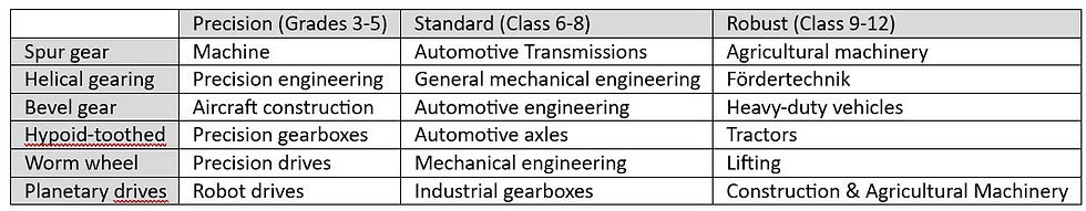
8. Matrix of gear classes and types
The matrix diagram presents the gear classes and types in a structured overview. The horizontal axis shows the type of gearing (spur gear, bevel gear, etc.), while the vertical axis represents the quality classes from precise to robust. Such a diagram gives a quick overview of the suitability and typical areas of application
This comprehensive analysis and consideration shows the versatile possibilities, requirements and challenges in the development and application of gears. With the new technologies and developments, gear technology will continue to play a key role in industrial applications in the future.
9. Materials for gears: properties, special features and process chains
The choice of material for gears is critical to the performance, durability and reliability of the gear components. Gears are exposed to high mechanical loads, friction and wear, so material selection and processing techniques play an important role. This section describes the most common materials, their specific properties, and typical process chains for gear manufacturing.
Typical materials for gears
Steels
Properties: Steels are the most commonly used materials for gearing. They offer high strength, toughness, and wear resistance suitable for dynamic and high-stress applications. In hardened form, they can also absorb high compressive stresses.
Typical steel grades: Commonly used steel grades include 16MnCr5 (an alloyed case-hardening steel for hardness and toughness), 20MnCr5 (higher carbon values for improved surface hardness), and 42CrMo4 (for greater hardness requirements and more stable components).
Process chain:
Forging or casting: Steels are often cast or forged in the desired basic shape.
Soft machining: Milling, turning or gear shaping for the pre-processing of teeth.
Hardening (e.g. case hardening or induction hardening): Increases the hardness of the tooth flanks and gives the teeth a wear-resistant surface.
Grinding or fine grinding: For high-precision applications and to improve surface quality.
Processing Instructions: When processing hardened steel, fine tolerances and precise surface finishes are required. The hardening processes must be carried out in a controlled manner in order to minimise hardening distortions.
Cast iron
Properties: Cast iron has good wear resistance and damping ability, making it suitable for low-speed, high-load applications. However, due to its high carbon content, it is more brittle than steel.
Typical castings: Gray cast iron (e.g. GJL-250) and ductile iron (e.g. GJS-400) are the most commonly used variants. Gray iron offers high wear resistance, while ductile iron offers better toughness and strength.
Process chain:
Casting into sand molds or metal molds to create the shape of the gear.
Mechanical processing (e.g. milling, turning, drilling): Post-processing to achieve precise tolerances.
Finishing as needed (e.g. sanding) to create a clean surface.
Processing instructions: Cast iron requires special milling tools and cooling methods because it tends to form fine chips that can be abrasive. In addition, attention must be paid to the brittle structure, which can lead to cracks at high impacts.
Synthetics
Properties: Plastics are lightweight, corrosion-resistant and cushionable. They are particularly popular in low-noise and low-load applications, such as household appliances and medical technology.
Typical plastics: Polyamide (PA), polyoxymethylene (POM) and polyetheretherketone (PEEK) are commonly used plastics. PEEK offers high temperature resistance and strength, while PA and POM are more cost-effective.
Process chain:
Injection molding or extrusion: To mold the gear out of the plastic.
Cooling and post-processing: For higher precision and post-processing when needed.
Smoothing and/or coating: If necessary, to further reduce surface friction.
Processing instructions: During injection molding, shrinkage and distortion must be taken into account, which can occur with plastics. Cooling processes must be precisely adjusted to minimize deformation.
Powder Metallurgy (PM) Materials
Properties: Powder metallurgical materials, such as sintered steel, are particularly suitable for mass production. They offer good strength and can be molded into complex shapes without the need for a lot of post-processing.
Typical powder metallurgical alloys: Sintered steel made of iron-based materials with small amounts of copper, molybdenum or nickel to improve strength and hardness.
Process chain:
Pressing: Metal powder is compacted in a mold under high pressure.
Sintering: The compacted workpiece is heated at a high temperature to fuse the metal particles together.
Hardening and post-processing: Hardening processes such as induction hardening or coatings increase wear resistance.
Processing instructions: The density and porosity of the sintered gears must be monitored, as this affects the mechanical properties. Finishing may be required to improve surface hardness and minimize roughness.
Light metals (e.g. aluminium, titanium)
Properties: Light metals are lightweight and offer a good strength-to-weight ratio. Aluminum and titanium alloys are corrosion-resistant and have high strength, making them suitable for aerospace and automotive applications.
Typical alloys: AlSi10Mg for aluminum and Ti-6Al-4V for titanium are widely used.
Process chain:
Casting or forging: production of the basic mould, often followed by mechanical processing.
Mechanical processing (milling, turning): For the precise design of the gearing.
Coating (e.g. anodising aluminium) to improve wear resistance and corrosion resistance.
Processing instructions: Light metals are sensitive to high temperatures and tend to deform if not processed properly. Cooling strategies must be carefully planned and applied to ensure even heat distribution.
Summary of the materials and their areas of application

Important processing considerations
Material processing plays a crucial role in producing gears with the desired mechanical properties. High precision, suitable hardness, wear resistance and the avoidance of cracks are essential factors influencing the manufacturing process. Typical processing challenges and requirements include:
Controlled hardening processes: Heat treatment is a critical step, especially for steels, to minimize cracking and warping.
Cooling processes: Controlled cooling processes are important for both metals and plastics to avoid warping and dimensional deviations.
Porosity control of sintered materials: the density of the material influences the strength; Pores can lead to premature material fatigue.
Avoidance of surface damage: Especially with titanium and aluminum, care must be taken to ensure that surfaces are not damaged by incorrect processing, as these metals are prone to cracking and corrosion.
Careful selection and processing of materials can produce gears that meet the specific requirements for service life, strength and efficiency. Gear materials science and manufacturing technology are constantly evolving to maximize the performance and efficiency of transmission systems.


Very helpful overview