Shaft hub connections in mechanical engineering: technologies, comparison and standards
- Wolfgang A. Haggenmüller

- Aug 6, 2025
- 8 min read
Updated: Aug 7, 2025
Introduction
Shaft hub connections are fundamental machine elements for the reliable and backlash-free transmission of torques in a wide range of rotating systems. They combine geometric and frictional principles to ensure concentricity, resilience and durability. This technical article provides a detailed overview of classic and modern connection technologies, explains technical designs, advantages and disadvantages, fields of application and manufacturing processes, and is based on recognized standards and expert opinions.

Technical definition and purpose of shaft hub connections
Shaft hub connections are essential machine elements that are used to transfer torque and rotary motion from a shaft to a hub or vice versa. The connection can be form-fitting and/or force-fitted:
Positive fit: Geometric toothing or shape fit prevents relative movement.
Adhesion: Frictional forces between the components ensure torque transmission.
The correct design ensures precise concentricity, sufficiently high torque capacity and minimizes notch effects. Shaft hub connections can be found in almost all rotating systems: electric motors, gearboxes, couplings, pumps and machine tools. Standards such as DIN 6885 (keys), DIN 5462 (spline shafts) and DIN 5480 (toothed shafts) provide the necessary dimensions and tolerances.
Tight fit vs. force fit
Positive fit is achieved by means of directly gripping elements (groove, toothing), which serve precise positioning and backlash-free torque transmission. Challenges include notching effects on flanks and tooth roots as well as manufacturing tolerances that can impair concentricity.
Adhesion uses frictional force through preload or press fit. The advantages are uniform stress distribution and reduced notching effect. The design requires precise friction coefficient calculations and control of the assembly forces.
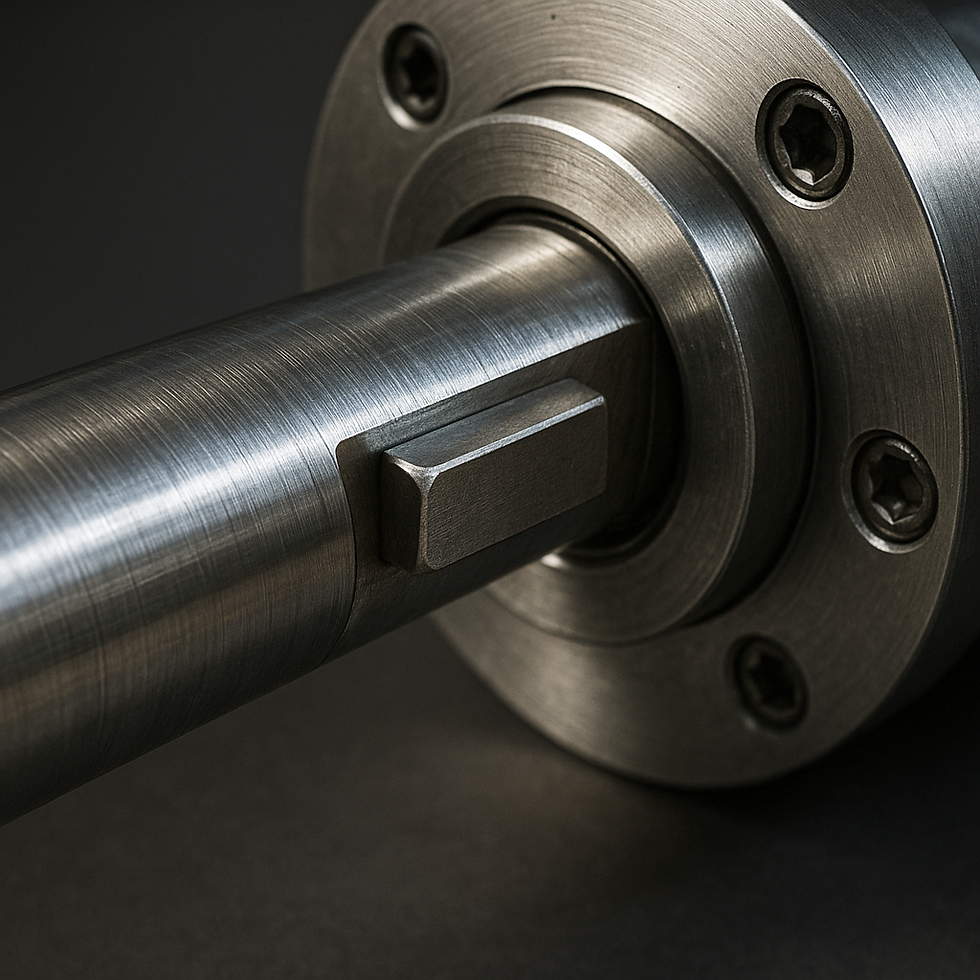
1. Key connection (DIN 6885)
Technical design and functionality
Key keys are rectangular key parts that engage in a shaft and hub groove. The keyway transmits torque through the side faces, while the groove fixes the axial position. Typical materials are soft steels (C15–C45) with a tensile strength of 400–600 N/mm². Manufacturing is done by milling or EDM for high dimensional accuracy.
Load separation and load analysis
After the Wöhler test and notch effect factor k_t, the permissible alternating bending at the groove base edge is tested. To increase the service life, a threadable round groove end (ground groove) for notch pitch is recommended.
Pros and Cons
Advantages: Cost-effective, standardized, easy assembly/disassembly.
Disadvantages: High voltage increase at the groove base, limitation to medium torques (up to approx. 5 kNm), backlash with toleranceexceedances.
Applications
Machines with moderate torque requirements such as fans, low-power gears, pulleys.
Manufacturing process
Shaft and hub machining: Milling of the key groove according to tolerance field JS9.
Keyway production: Grinding to measure, surface hardening to 40–50 HRC optional.
Expert quote: "A precisely manufactured key key is crucial for the service life of drive shafts." – Prof. Dr.-Ing. Müller, Technical University of Munich.
2. Wedge connection (DIN 5462 / ISO 14)
Technical design and functionality
Wedge joints use a helical splined wedge (pitch angle approx. 1:100), whichtransmits forces both in a form-fit and force-fit manner. The grooves are pre-milled with drop-forged blanksand then precisely ground.
Load distribution and self-locking
The sloping surfaces create axial components of the pressing force, which cause self-locking. The friction part force F_r = F_N · tan(α) must be calculated to prevent loosening under load.
Pros and Cons
Advantages: High frictional content, lower notch effect than keyway, low-maintenance.
Disadvantages: Limited concentricity (< 0.02 mm), limited speed (< 1,200 1/min), additionalsafety element against axial backlash necessary.
Applications
Agricultural machinery, gearboxes in rolling mills, heavy conveyors.
Manufacturing process
Milling (profile milling cutters) and grinding of keyways.
Material: C45/42CrMo4 at higher loads.
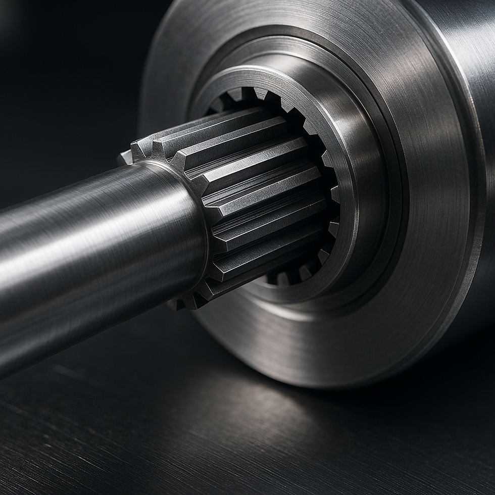
3. Toothed shaft connection (DIN 5480 / DIN 5481)
Technical design and functionality
Involute toothed shaft profiles allow high torques (up to 50 kNm) and exact positioning. The gear parameters (module, pitch circle diameter, tooth height) are calculated according to DIN 5480. The flank rounding at the tooth base reduces notch stresses.
Manufacturing and post-processing steps
Hobbing / Generating grinding for profile generation.
Heat treatment: induction hardening or case hardening (hardening depth 0.8–1.2 mm).
End grinding for low surface roughness value (R_z < 4 μm).
Pros and Cons
Advantages: Very high power density, precise concentricity (< 0.01 mm), long service life.
Disadvantages: High production and tool use, increased notch tension factors. Disadvantages could be elimimated by axial forming.
Applications
Automotive transmissions, Heavy transmissions, shaft couplings, wheel hub drives in commercial vehicles, automotive
Expert quote: "Involute gears are the basis of modern drive technology and enable maximum performance with smooth running at the same time." – Prof. Dr.-Ing. Weber, RWTH Aachen University.
4. Press connection (H7/p6)

Technical design and functionality
The hub is pressed onto the shaft with a tight clearance fit (clearance range H7/p6). The pressing force F_p is calculated from the frictional force and the necessary torque transmission: M = F_p · µ · r.
Assembly processes
Hydraulic press with defined force-pressure cycle.
Thermal mounting: Heating the hub to 150-200°C or cooling the shaft.
Pros and Cons
Advantages: Completely backlash-free, even load distribution, high torque capacity.
Disadvantages: Complex assembly, possibly destructive removal.
Applications
Turbine rotors, turbocharger shafts, precision gearboxes in robotics.
5. Clamp connection (clamping ring systems)

Technical design and functionality
Clamping rings (one- or two-piece) create a ring-shaped preload on the hub by means of a conical sleeve. The clamping force can be precisely controlled by torque monitoring of the screws (torque dispersion ± 5%).
Design parameters
Cone angle: 1:10 to 1:12
Preload force: calculated according to F_v = M/μ/r
Pros and Cons
Advantages: Resoluble, no thermal effort, low notching effect.
Disadvantages: Higher part costs, regular check of the preload necessary.
Applications
Servo motors, CNC tool interfaces, transducers.
6. Shrink connection

Technical design and functionality
The shrink connection is a thermally supported press connection: the hub is heated to 200 °C, placed on the shaft, and frictional friction is created when it cools down. The resulting pressing force is 5–10 kN/cm².
Pros and Cons
Advantages: Very high pressing force with even force distribution, without notching effect.
Disadvantages: Thermal stress on the material, slower assembly cycle.
Applications
Flywheels, electric motor rotors, turbocharger shafts.
7. Polygonprofile (DIN 32711)

Technical design and functionality
Multi-edge profiles (P1G to P8G) provide 4-8 contact surfaces that transmit torque without traditional notching. The profiles are produced by generating cutting and offer concentricities of up to 0.005 mm.
Pros and Cons
Advantages: Simplified installation, high power density, reduced notch stresses.
Disadvantages: Expensive tools, low standardization outside DIN.
Applications
High-performance gearboxes, aircraft engines, robot joints.
8. EKagrip®Connection
Technical design and functionality
EKagrip® film is a diamond-structured intermediate layer that increases the coefficient of friction μ by a factor of 1.5–2. The micro-gear elements interact with the surface roughness.
Pros and Cons
Advantages: Higher torque transmission with the same pressing force, corrosion protection (flanging corrosion prevention).
Disadvantages: Additional costs, foil thickness affects fit size.
Applications
Compact drive systems, hard-to-reach crimp connections, field can be retrofitted.
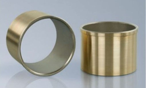
Illustration: Direct coating with EKagrip on a shaft-hub connection Source: ESK
Expert quote: "The targeted use of diamond-structured films can raise friction coefficients in press joints to a new level – EKagrip® is leading the way here." – Wolfgang A. Haggenmüller.
Further reading:
Haggenmüller, W. A.: "Friction Coefficient Improvement in Press Joints with Diamond-Coated Foils", Tribology International, Vol. 156, 2023.
Schubert, M. and Klein, H.: Modern friction closures in mechanical engineering, Springer Vieweg, 2022.
Müller, T. et al.: "Laboratory investigations on the resistance of EKagrip® coatings", Wear, Vol. 512, 2024.
Comparison of connection types
Connection | Torque Capacity | Concentricity | Assembly | Resolubility | Cost |
Key | up to 5 kNm | 0.02–0.05 mm | small | yes | low |
Wedge connection | up to 10 kNm | 0.02 mm | medium | yes | low |
Tooth shafts | 10–50 kNm | 0.005–0.01 mm | high | depending on the design | high |
Press connection | > 50 kNm | 0.005 mm | very high | seldom | medium–high |
Clamp connection | 5–20 kNm | 0.01–0.02 mm | medium | yes | medium |
Shrink connection | > 50 kNm | 0.005–0.01 mm | high | seldom | medium |
Polygon profile | 20–100 kNm | 0.002–0.005 mm | very high | yes | very high |
EKagrip® | +50% friction coefficient | same as basic connection | small | yes | medium |
Normative foundations
DIN 6885 Keys: Stress Analysis and Notch Effect Factor (Prof. Dr.-Ing. Müller, Technical University of Munich).
DIN 5462 Spline Shafts: Friction Part Force Calculation (Dr.-Ing. Schmidt, Fraunhofer IWU).
DIN 5480 Toothed shafts: Gear optimization by flank machining (Prof. Dr. Weber, RWTH Aachen University).
Market
Here are some market-related key figures for shaft hub connections (often summarized under the generic term "ShaftLocking Devices" or "Shaft Couplings"):
Global market for ShaftLocking Devices
According to a recent report, the global market for ShaftLocking Devices was valued at USD 1.2 billion in 2023. appreciated. By 2032, it is expected to rise to USD 2.3 billion.at a compound annual growth rate (CAGR) of 7.1%. Dataintelo
Alternative market assessment
A second survey estimates the same market at USD 2.5 billion for 2022. and forecasts a CAGR of 5.6% between 2023 and 2030. Google Sites
Special look at shaft couplings
The "shaft coupling" submarket (couplings as a subset of shaft hub connections) reached a value of USD 202 million in 2023. and is expected to grow to USD 304.8 million by 2033. (CAGR 4.2%). thebrainyinsights.com
Explanation of the differencesThe different market volumes result mainly from different scope definitions (e.g. including purely force-fitsolutions vs. all form‑ and adhesion connections) and survey methods. What all studies have in common, however, is significant growth, driven by:
· Increasing automation and Industry 4.0
· Higher demands on precision and reliability
· Expansion of infrastructure projects and renewable energies
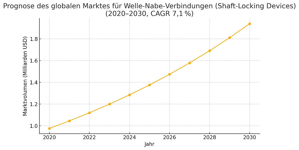
The chart below shows the projected development of the global ShaftLocking Devices market from 2020 to 2030 based on a compound annual growth rate (CAGR) of 7.1%
Market segmentation by region and application industry
A detailed look at the global wave hub connection market shows regional and sectoral differences in demand and growth expectations:
Regional breakdown (2023)
AsiaPacific (APAC): ~40% – Leading the way thanks to rapid industrialization and infrastructure investment in China and India (globenewswire.com, dataintelo.com).
Europe: ~25% – Stable demand in automotive and engineering hubs such as Germany and Italy.
North America: ~20% – Driven by retrofits in the food and packaging industries.
Latin America: ~8% – Growing heavy industry, but limited investment volumes.
Middle East & Africa (MEA): ~7% – Fluctuating demand due to oil market cycles.
Segmentation by application industry
Packaging machines: ~30% – High demand for precise shaft hub connections to ensure positioning accuracy (github.com).
Conveyor Machinery: ~25% – Robust, low-maintenance connections for continuous operation.
Printing & Converting Technology: ~15% – Specialized joints for precise register and drive.
Wood and metalworking machines: ~10 % – Classic keyless and wedge joints dominate.
Automotive & Special Applications: ~20 % – Used in clutches, steering systems and rotor shafts of special drives.
These market segments underline the importance of industry-specific selection and knowledge of standards in order to design the optimal connection system. More precise values can be found in corresponding regional and segment studies
Result
The variety of shaft hub connections allows for a tailor-made design for every requirement. While traditional keyways and wedge joints offer cost-effective solutions for medium torques, toothed shafts and polygon profiles allow for high power densities with high precision. Force-fit processes such as press and clamp connections score points with a low notch and zero backlash. Technologies that increase the friction coefficient, such as EKagrip®, complement the range with an economical increase in torque capacity. In-depth knowledge of standards and precise production planning are the keys to reliable and long-lasting connections.
Literature
DIN 68851: Keys – Steel – Dimensions and tolerances (Wilh. Wernecke GmbH & Co. KG)
DIN 5462/ISO 14: Spline Shaft Connections – Dimensions, tolerances, testing (din-en)
DIN 5480: Splines with Involute Flanks – Dimensions, Profile Control (spn-drive.de)
DIN 327111/2: Shaft hub connection– Polygon profile P3G (din-en)
EKagrip® FRICTIONPOLISHING COATINGS IN FORCE-FIT JOINTS, ResearchGate (ResearchGate)
Optimization Possibilities of Gears and Sprockets, Clausthal University of Technology (IMW)


Comments